woodworking homemade shopmade
HOMEMADE MINI METAL LATHE
As usual I suddenly decided to build up a mini metal lathe. I have now a metal lathe made in Taiwan, quality of which is too poor, but recently it got more poorer, its motor has been broken, eventually out of use. Now I replaced the motor but far from useable condition.
I also have a small metal lathe made in Austria, but this unit is small to process only the small works.
On the other hand, I started building a metal lathe to process necessary sized works. I stopped about 3 years ago. Problem is that my power tools such as drill press, lathe etc. are not with enough accuracy, and needless to say, my skill is out of question. However I will start the work when it becomes worm. The following photos are the half way built lathe.
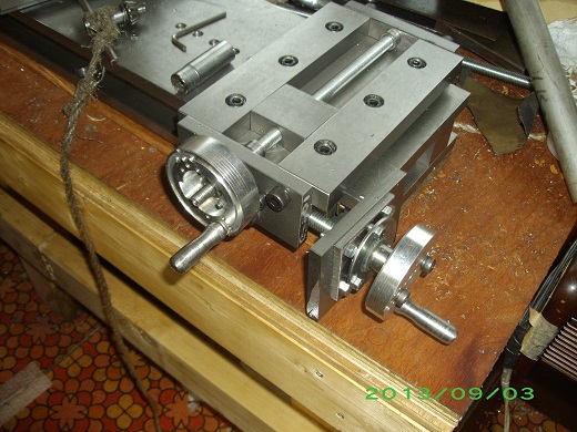
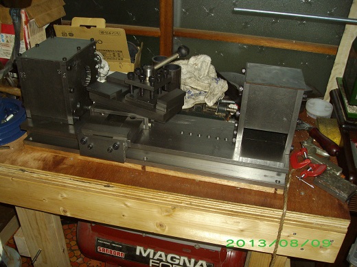
It took about a half year. The finishing will take longer as it would be the most complicated and hard process. I will show it on this site when completed.
Anyway I thought I would be able to get the good hints of building the lathe by building a small lathe, so I started this project.
There are some people building such metal lathe, but I could not on net, almost of them are professional, good tools and machines to process, therefore I cannot same way. Also some people build the lathe using aluminum casting. Problem is that I cannot process the cast components, and I don't trust material strength of cast aluminum.
Therefore I purchased the polished soft steel blocks in standard, and cut them in size, assembling by bolt. Anyway I thought I need to get experience to understand the important point in building such unit.
As usual I got the material from the junk box, such as the flat bar, angle rod, bolt etc. except the bearings which I newly purchased..
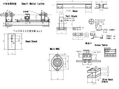
I sketched the simple design.
I used the sewing machine motor which is a little too big for this lathe. Usually in such lathe, gear change or pulley change to control speed. By this speed selection, the necessary torque is secured in low speed. I control the motor speed by voltage adjuster transformer, therefore the big motor is necessary to secure the necessary torque in low speed.
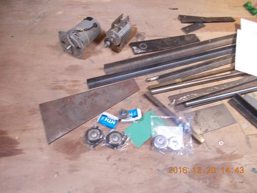
I cut, polished, bolted, riveted these material...
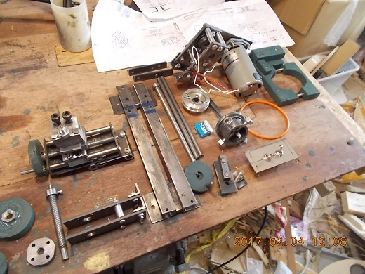
Such units are made.
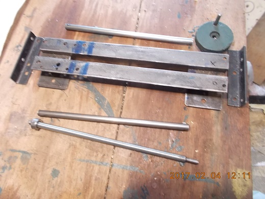
This is the base. Lenght is approx. 300mm. Accembled the 20 and 25mm angle by bolt.
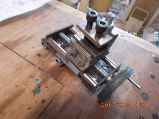
The cross table and bite rest.
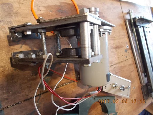
The head stock assembled with the motor.
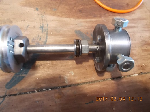
This is the main shaft. Drive pulley used to be the head drum taken from old VCR. Homemade 4 jaw chuck (4 screw chuck?). The face plate is behind the chuck for center-center processing. Main shaft diameter is 12mm. It has no through hole, but a dead center.
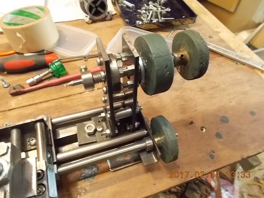
This is the tale stock. 12mm bold can be moved back and forth by the knob and fixed at any position. This stock itself can be fixed at any position on the base. 12mm bold has a dead center. Also 6mm drill chuck can be set instead of the dead center. However the accuracy of the drill chuck is not satisfactory.
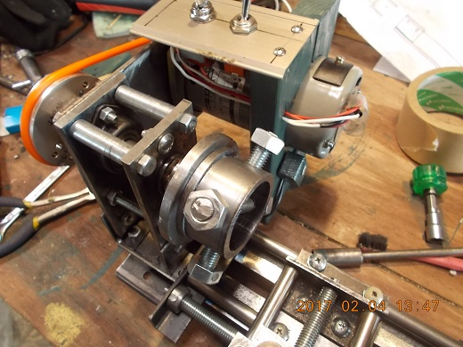
The head stock is mounted on the base. Power SW and reverse SW are mounted on the motor. So far speed control is by voltslider. If necessary, It is possible to make a 0-100v adjustable unit, but I don't think it is necessary.
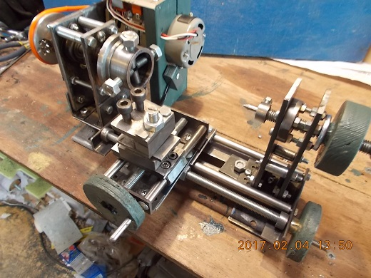
Completed unit. It looks good, but performance is bad. So far satisfied accuracy is not available. The total consttruction is not enoug rigid, I suppose.
I will try to improve, and wish to up the video on the site.
To the next
Return
Article Index
Return to Home